The Johnson Counter: A Twisted-Ring Counter Explained
A Johnson counter is a shift register with the inverted last output fed back to the first stage, giving 2n states from n flip-flops and 2-input decoding.

TL;DR: A Johnson counter is a synchronous shift register where the inverted output of the last stage feeds back to the first stage. With flip-flops it produces unique states, and any state can be decoded with a single 2-input AND gate — far simpler than the wide AND tree a binary counter requires.
A Johnson counter sits between a binary counter (compact but hard to decode) and a ring counter (trivial to decode but wasteful). By feeding the inverted last output back to the first input of a shift register, the design doubles the available states without any extra gates and produces a sequence that any 2-input AND can decode glitch-free.
The Architecture of the “Twist”
At its core, a Johnson counter is a synchronous shift register where the inverted output of the last stage is fed back into the input of the first stage. If you’re familiar with a standard ring counter, you know that it typically circulates a single “1” through flip-flops, giving you states.
The Johnson counter changes the game. By feeding back instead of , we create a sequence where “1”s fill up the register and then “0”s fill it back up. This simple modification results in states using only flip-flops.
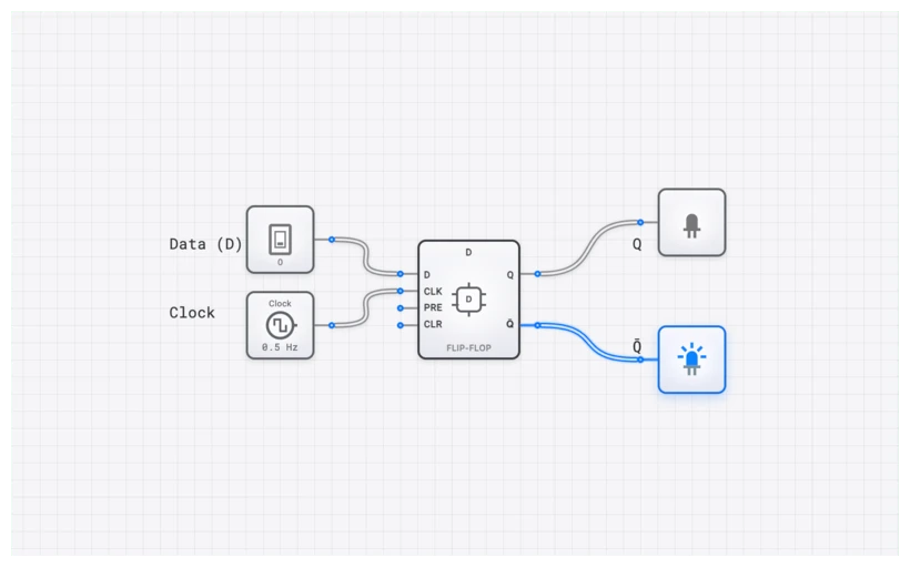
In digisim.io, you can build this using a series of D_FLIP_FLOP components. The feedback loop is the critical part: the output of the final D_FLIP_FLOP must connect back to the input of the first D_FLIP_FLOP in the chain. This “twist” in the feedback path is what gives the counter its name and its unique properties.
Explore the D_FLIP_FLOP Component
Technical Specification: The 4-Bit Sequence
Let’s look at the state sequence for a 4-bit Johnson counter. We’ll assume the register starts cleared at 0000. In this configuration, we have four stages (), which provides distinct states.
| Clock Pulse | State Description | ||||
|---|---|---|---|---|---|
| 0 (Reset) | 0 | 0 | 0 | 0 | All Zeros |
| 1 | 1 | 0 | 0 | 0 | First “1” enters |
| 2 | 1 | 1 | 0 | 0 | Filling with “1”s |
| 3 | 1 | 1 | 1 | 0 | Filling with “1”s |
| 4 | 1 | 1 | 1 | 1 | All Ones |
| 5 | 0 | 1 | 1 | 1 | First “0” enters |
| 6 | 0 | 0 | 1 | 1 | Filling with “0”s |
| 7 | 0 | 0 | 0 | 1 | Filling with “0”s |
| 8 | 0 | 0 | 0 | 0 | Back to Start |
The characteristic “walking” pattern is obvious here. The bits shift right on every clock edge, but the new bit entering is always the inverse of what was just in . This means it takes four clock cycles to fill the register with ones, and another four to empty it back to zeros.
The Boolean Foundation
The logic governing the feedback is straightforward. For an -bit counter where is the last stage and is the first:
The decoding logic is where the Johnson counter truly shines. Unlike a binary counter, which requires an -input AND gate to decode a specific state (for example, a 4-input gate for a 4-bit counter), a Johnson counter only ever requires a 2-input AND gate to decode any of its states.
This is because each state is uniquely identified by the transition between a “1” and a “0” (or vice versa) at a specific point in the register.
Example: Decoding State 3 () To detect this state, we look for the point where the “1”s have filled up to , but is still “0”.
This reduction in “glue logic” is a massive advantage when you’re building hardware on a tight budget of gates or silicon area.
Common Pitfall: Invalid States and Self-Correction
A common source of frustration when building Johnson counters in hardware is erratic behavior caused by unused states.
A 4-bit register has possible states. A 4-bit Johnson counter only uses 8 of them. What happens to the other 8? If your circuit powers up into an invalid state like (alternating bits), the standard feedback loop will just cycle through other invalid states () and never join the main sequence. This is a classic “lock-up” condition.
In a professional design, we add self-correcting logic. The simplest approach detects invalid states with combinational logic and asynchronously resets the register. For a 4-bit Johnson counter the eight valid patterns are , , , , , , , — any other pattern (such as the lock-up) is invalid. A small comparator can pull the RST line high whenever the register lands on a non-valid state, returning the counter to its start on the next clock edge.
You can also build the correction directly into the feedback equation, but be careful: naïve single-gate modifications often break the valid sequence as well. For example, replacing with might seem equivalent on the valid path, but it actually forces a into at the valid state — derailing the sequence into instead of . Always verify any candidate feedback expression against all valid states before relying on it.
Visualizing with the Oscilloscope
One of the most beautiful aspects of the Johnson counter is the phase relationship between its outputs. Each flip-flop output is a square wave with a frequency of , where is the clock frequency. However, each successive output is shifted by exactly one clock period.
If you place an OSCILLOSCOPE_8CH in digisim.io across the outputs of a 4-bit Johnson counter, you’ll see a perfect “staircase” of overlapping pulses. Each output has a 50% duty cycle. This is a massive advantage over the narrow, spike-like pulses produced by a standard ring counter, especially when driving power electronics or LEDs.
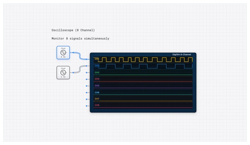
Using the OSCILLOSCOPE_8CH is critical for verifying the timing. You can see the propagation delay () as the signal moves from one D_FLIP_FLOP to the next. In a high-speed system, these nanoseconds matter.
Open Johnson Counter Building Block
Real-World Applications
Why do we bother with this “twisted” logic in the age of cheap microcontrollers? Because in high-speed digital design and power electronics, hardware-level timing is everything.
- The CD4017 Decade Counter: This is perhaps the most famous implementation of a Johnson counter. Internally, it uses a 5-bit Johnson counter to create 10 decoded outputs. It’s the heart of thousands of “LED chaser” circuits and simple timers.
- Multi-Phase Clock Generation: If you need to trigger four different events in a specific sequence with non-overlapping pulses, a Johnson counter is the most stable way to do it. It provides inherent glitch-free decoding.
- Stepper Motor Control: Stepper motors require specific sequences of energized coils (e.g., Phase A, then Phase B, then Phase A’, then Phase B’). A Johnson counter can generate these power phases directly with minimal glue logic, ensuring the motor turns smoothly without complex software overhead.
Building it Yourself: A digisim.io Walkthrough
The walkthrough uses D_FLIP_FLOP components — predictable behavior and easy to chain.
- Layout: Place four D_FLIP_FLOP components in a row.
- Clocking: Connect a single CLOCK source to the clock input of all four flip-flops. Remember, this is a synchronous counter, so they must all trigger at the exact same time.
- The Chain: Connect to , to , and to .
- The Twist: Place a NOT gate. Connect to the input of the NOT gate, and the output of the NOT gate back to . This completes the “switch-tail” feedback.
- Output: Attach an OUTPUT_LIGHT to each output to see the “walking” pattern.
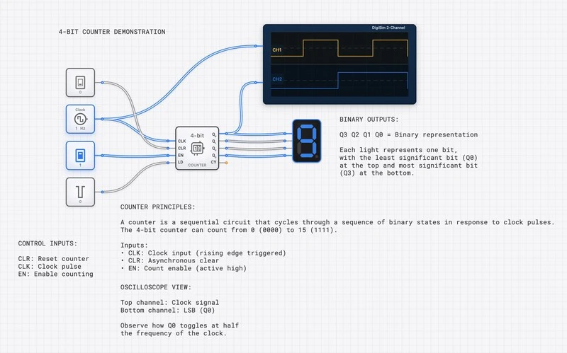
- Analysis: Add an OSCILLOSCOPE to and . You’ll notice that is exactly 4 clock cycles behind .
Curriculum Integration
If you are following our structured learning path on digisim.io, the Johnson counter represents a pivotal moment where we move from simple data storage to complex state machines. It bridges the gap between basic registers and the Control Units used in CPUs.
- Introduction to D_FLIP_FLOP behavior.
- Shift Register fundamentals.
- The Ring Counter vs. The Johnson Counter (This Article).
- Designing Finite State Machines (FSMs).
Final Thoughts
A small change in topology produces a significant increase in capability. The Johnson counter is more efficient than a ring counter and easier to decode than a binary counter, making it ideal for LED chasers, multi-phase clock generation, and stepper motor control.
For the next step, read Mastering Frequency Division for modulo-N counter design, or Mastering Shift Registers for the underlying chained-flip-flop architecture. Open the D_FLIP_FLOP component reference to start building.