The JK Flip-Flop: Universal Sequential Building Block
The JK flip-flop has four modes — hold, set, reset, toggle — selected by J and K at each clock edge. It's the universal cell of counters and state machines.

TL;DR: The JK flip-flop is the most versatile 1-bit memory element. Its J and K inputs at the active clock edge select one of four modes — hold (00), reset (01), set (10), and toggle (11). Its characteristic equation is . Crucially, it eliminates the SR latch’s forbidden state by repurposing as a useful toggle.
The JK_FLIP_FLOP solves the SR latch’s forbidden-state problem and gives us a single component that can hold, set, reset, or toggle on each clock edge. That four-mode flexibility makes it the canonical building block for ripple counters, state-machine registers, and anywhere a D flip-flop plus extra logic would otherwise be needed.
From Ambiguity to Universality: The Evolution of the JK_FLIP_FLOP
To appreciate the JK_FLIP_FLOP, look back at the SR_LATCH. The SR (Set-Reset) Latch is effective for basic storage, but it has a “forbidden” state when both Set and Reset are asserted simultaneously (). In a physical circuit, this creates an unpredictable, unstable output — a cardinal sin in digital design, where determinism matters. Students often spend hours debugging “ghost” signals before realizing they accidentally triggered an SR invalid state.
The JK_FLIP_FLOP is a clocked, synchronous device that directly confronts this ambiguity. It retains the familiar Set and Reset functions but redefines the problematic input condition into something incredibly useful: the toggle state.
This single innovation transforms it from a simple memory cell into a powerful tool for counting, frequency division, and state machine implementation. Because it operates on the edge of a clock signal, state changes happen at precise, predictable moments. It brings order to the chaotic flow of data.
Technical Specification: The Four Modes of Operation
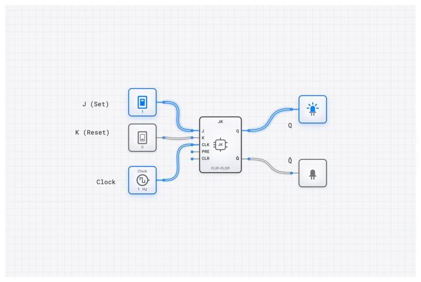
The standard JK_FLIP_FLOP has two primary data inputs, J (analogous to Set) and K (analogous to Reset), a CLOCK input, and the complementary outputs Q and Q’. Its behavior is defined by the state of J and K on the rising edge of the clock pulse.
In digisim.io, the JK_FLIP_FLOP is edge-triggered. This means it ignores the inputs until the exact moment the CLOCK signal transitions from Low to High. This is a critical distinction from a latch, which is level-sensitive.
| J Input | K Input | Current State (Q) | Next State () | Action |
|---|---|---|---|---|
| 0 | 0 | 0 | 0 | Hold (No Change) |
| 0 | 0 | 1 | 1 | Hold (No Change) |
| 0 | 1 | 0 | 0 | Reset |
| 0 | 1 | 1 | 0 | Reset |
| 1 | 0 | 0 | 1 | Set |
| 1 | 0 | 1 | 1 | Set |
| 1 | 1 | 0 | 1 | Toggle |
| 1 | 1 | 1 | 0 | Toggle |
The “Hold” state makes it a memory device. “Set” and “Reset” allow for direct control. But the “Toggle” state is its signature feature. When both J and K are High, the output flips its current state. If it was 0, it becomes 1. If it was 1, it becomes 0. This is the foundation for every binary counter ever built.
The Logic Within: The Characteristic Equation
The behavior of the JK_FLIP_FLOP is perfectly captured by its characteristic equation. This equation describes the next state of the output, , as a function of its current state, , and the inputs, and .
Let’s verify each of the four modes against this equation:
1. Hold (J=0, K=0): The output retains its current value. This is the memory mode.
2. Set (J=1, K=0): The output is forced to ‘1’ regardless of the current state. Note the Boolean identity: .
3. Reset (J=0, K=1): The output is forced to ‘0’ regardless of the current state.
4. Toggle (J=1, K=1): The output inverts. If Q was ‘0’, it becomes ‘1’. If Q was ‘1’, it becomes ‘0’.
The toggle mode is what makes the JK Flip-Flop uniquely powerful. Where the SR Latch’s condition produces chaos, the JK Flip-Flop’s condition produces a perfectly deterministic and useful behavior. The internal feedback connections from Q and back to the input AND gates are what make this possible—they prevent the race condition that plagues the SR design.
Common Pitfall: Timing, Race-Around, and Metastability
A JK_FLIP_FLOP is a powerful tool, but it’s not magic. It’s governed by strict timing rules. If you ignore them, your simulation might look fine, but your real-world hardware will fail.
Setup and Hold Times
The J and K inputs cannot change at the exact moment the clock ticks. They must be stable for a brief period before the clock edge () and remain stable for a period after the edge (). If you violate these timings, the flip-flop can enter a metastable state—an unstable, intermediate voltage level that is neither a clear 0 nor a 1. Eventually, it will collapse to a random state, but in that window of uncertainty, your logic gates might interpret the signal differently, leading to catastrophic system failures.
The Race-Around Condition
This is a classic issue in older, level-triggered JK latch designs. If the clock pulse is “High” for too long, the output can toggle, and that new output can race back to the inputs (via the internal feedback loops) and cause another toggle, all within the same clock pulse. The output ends up oscillating wildly.
Modern components on digisim.io, like the JK_FLIP_FLOP, are edge-triggered. They only respond to the instantaneous transition of the clock. This completely eliminates the race-around condition. However, when building complex systems, you should still use an OSCILLOSCOPE to verify that your clock pulses are clean and your propagation delays aren’t stacking up in a way that creates “glitches.”
Building and Verifying on digisim.io
Theoretical knowledge becomes practical skill only through hands-on application. Let’s build a circuit to prove the JK_FLIP_FLOP’s most famous behavior: frequency division.
- Open the Editor: Navigate to the digisim.io circuit editor.
- Place Components: Drag and drop a JK_FLIP_FLOP, a CLOCK, two CONSTANT sources, and an OSCILLOSCOPE_8CH.
- Configure for Toggle Mode: Click on both CONSTANT components and set their values to 1 (High). Connect one to the J input and the other to the K input of the JK_FLIP_FLOP. This puts the flip-flop into permanent toggle mode.
- Connect Clock and Output: Wire the CLOCK component to the CLK input of the flip-flop. Wire the Q output of the flip-flop to Channel 2 of the OSCILLOSCOPE_8CH. Connect the raw CLOCK signal to Channel 1.
- Run and Observe: Start the simulation.
Verification with the OSCILLOSCOPE_8CH
The OSCILLOSCOPE_8CH is your best friend for debugging sequential logic. By comparing the clock and the output, you’ll see something remarkable: The waveform on Channel 2 (the Q output) will have a frequency that is exactly half that of the waveform on Channel 1 (the clock).
For every two clock ticks, the output completes only one full cycle. You have just built a divide-by-2 circuit. If you chain another JK_FLIP_FLOP to the output of the first, you’ll get a divide-by-4 circuit. This is exactly how digital watches and timers work—they take a high-frequency crystal oscillator and “divide” it down until they have a 1Hz signal for the seconds hand.

Real-World Applications: Where History Was Made
The JK_FLIP_FLOP isn’t just a textbook component; it was the workhorse of the digital revolution.
1. Asynchronous Counters (Ripple Counters)
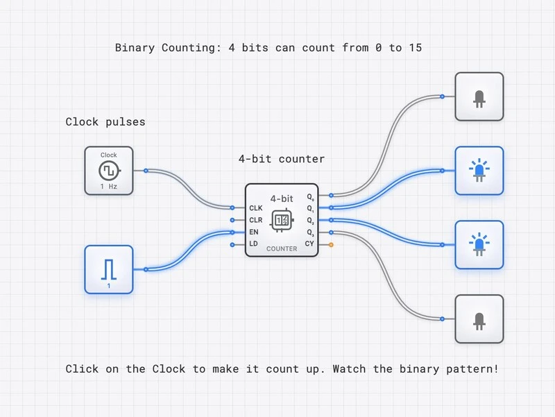
The iconic 7493 4-bit binary counter, a staple of the TTL logic family used in everything from early calculators to industrial controllers, was built by chaining JK_FLIP_FLOPs. By connecting the Q output of one flip-flop (in toggle mode) to the clock input of the next, you create a “ripple” effect. These were used everywhere, including early arcade games like Pong to manage scoring and screen refresh timing.
2. Finite State Machine (FSM) Control Logic
Before microcode became the standard, the control units of early microprocessors like the Zilog Z80 and Intel 8080 were implemented as complex, hardwired finite state machines. The JK_FLIP_FLOP was the ideal choice for this.
Why? Because its excitation table contains “don’t care” conditions. When designing the combinational logic to drive the flip-flops, these “don’t cares” allow for significant Boolean simplification. In the 1970s, when every gate on a silicon chip was expensive, using JK_FLIP_FLOPs instead of D_FLIP_FLOPs could save enough space to fit an extra register or instruction on the chip.
The “Universal” Flip-Flop: Converting to Other Types
One of the reasons I call the JK_FLIP_FLOP “universal” is that it can easily mimic any other type of flip-flop. This is a common exam question, but it’s also a practical skill when you’re limited by the components available in a specific logic family.
- To make a D_FLIP_FLOP: Connect the D input directly to J, and connect the inverse of D (using a NOT gate) to K. Now, the flip-flop will only ever be in “Set” or “Reset” mode, effectively latching the D value on the clock edge.
- To make a T_FLIP_FLOP: Simply tie J and K together. The single input now acts as a “Toggle Enable.” If the input is High, it toggles; if Low, it holds.
Integrating with the digisim.io Curriculum
Mastering the JK_FLIP_FLOP is a major milestone. It’s the bridge between simple “memory” and “computation.” This concept ties directly into our structured learning path:
- Prerequisites: This builds on the SR latch, D latch, and D flip-flop.
- Comparison: For the SR/JK comparison head-to-head, see SR vs. JK Flip-Flops.
- Future Applications: From here, build counters and state machines and shift registers.
Your Turn: Build, Test, and Master
Three exercises in the digisim.io editor:
- Build the Universal Component: Using a JK_FLIP_FLOP and a NOT gate, build a functional D_FLIP_FLOP. Test it with an INPUT_SWITCH.
- Construct a Ripple Counter: Chain three JK_FLIP_FLOPs together to build a 3-bit asynchronous counter. Use the OSCILLOSCOPE_8CH to view the CLOCK and the three Q outputs.
- The Modulo Challenge: Modify the 3-bit counter to create a modulo-6 counter (counts 0 to 5 and resets). Hint: detect the binary state ‘110’ with an AND gate and route that signal to the reset pin.
For the next step, read Mastering Frequency Division to extend toggle behavior into modulo-N counters, or The T Flip-Flop for a single-input view of toggling. Open the JK_FLIP_FLOP component reference to verify each of the four modes.