The XOR Gate: Mastering the Logic of Difference
The XOR gate outputs 1 when its inputs differ. It's the core of binary addition, parity checking, controllable inversion in subtractors, and the one-time pad.

TL;DR: The XOR (Exclusive OR) gate outputs 1 only when its inputs differ. Boolean expression . XOR is binary addition modulo 2, the sum bit of a half adder, the basis of parity checking, the controllable inverter in subtractors, and the engine of XOR-based encryption.
The XOR gate detects difference: it outputs HIGH only when its inputs disagree. While AND asks “both?” and OR asks “either?”, XOR asks “are these different?” That single question is the foundation of binary addition, error detection, controllable inversion in subtractors, and the one-time pad in cryptography.
What is an XOR Gate? The Logic of Difference
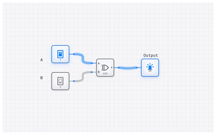
At its core, an XOR gate is a digital logic gate that produces a HIGH output (1) only when its inputs are dissimilar. If the inputs are the same—both HIGH or both LOW—the output is LOW (0). This “exclusive” nature is what distinguishes it from a standard OR gate, which would output HIGH if one or both inputs were HIGH.
Think of it as a strict “one or the other, but not both” rule. In a world of binary choices, the XOR is the ultimate arbiter of inequality.
Technical Specification: The Truth Table
The behavior of a 2-input XOR gate is perfectly captured by its truth table. Let’s denote the inputs as and , and the output as .
| Input A | Input B | Output Y | Description |
|---|---|---|---|
| 0 | 0 | 0 | Inputs are the same (LOW) |
| 0 | 1 | 1 | Inputs are different |
| 1 | 0 | 1 | Inputs are different |
| 1 | 1 | 0 | Inputs are the same (HIGH) |
The pattern is unmistakable: the output is 1 if and only if the inputs are not equal. This makes the XOR gate an ideal “Difference Detector.”
The Boolean Expression
In Boolean algebra, the XOR operation is represented by the symbol . The equation for the output is:
This is the shorthand we use in high-level design. However, to understand how to build an XOR gate from more basic components like AND, OR, and NOT, we can expand this expression into its Sum-of-Products (SOP) form. This form directly translates from the truth table rows where the output is 1:
This equation reads: “The output is HIGH if (NOT A is HIGH AND B is HIGH) OR (A is HIGH AND NOT B is HIGH).” If you were to build this using discrete gates on digisim.io, you’d need two NOT gates, two AND gates, and one OR gate. The XOR component simplifies this entire sub-circuit into a single, efficient block.
Common Pitfall: The Multi-Input Misconception
The 2-input XOR is a “difference detector.” When a third input is added, it is tempting — and wrong — to assume the gate outputs 1 only when exactly one of the three inputs is 1.
That is not how digital logic works.
A multi-input XOR gate functions as an odd-parity detector. It outputs 1 if there is an odd number of HIGH inputs. Let’s look at the 3-input truth table to see why:
| A | B | C | Count of 1s | |
|---|---|---|---|---|
| 0 | 0 | 0 | 0 | 0 (Even) |
| 0 | 0 | 1 | 1 | 1 (Odd) |
| 0 | 1 | 0 | 1 | 1 (Odd) |
| 0 | 1 | 1 | 0 | 2 (Even) |
| 1 | 0 | 0 | 1 | 1 (Odd) |
| 1 | 0 | 1 | 0 | 2 (Even) |
| 1 | 1 | 0 | 0 | 2 (Even) |
| 1 | 1 | 1 | 1 | 3 (Odd) |
Why does this happen? It’s due to the associative property of XOR: . The circuit essentially cascades the XOR logic. The first gate checks if A and B are different. The second gate then checks if that result is different from C.
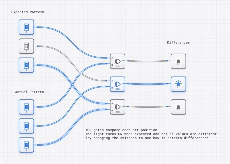
This behavior is fundamental to error-checking algorithms. If you’re sending data across a noisy wire, you can use XOR logic to generate a “parity bit” that tells the receiver whether the number of 1s should be even or odd. If a single bit flips during transmission, the XOR sum changes, and you’ve caught an error.
Hands-On: The Controllable Inverter
One of the most elegant uses of an XOR gate is as a “Controllable Inverter.” This is a trick used in almost every Arithmetic Logic Unit (ALU) to perform subtraction using addition logic.
Imagine you have two inputs: Data and Control.
- If Control is 0: . The signal passes through unchanged.
- If Control is 1: . The signal is inverted.
By toggling a single control line, you can turn a buffer into an inverter. This is how a CPU decides whether to add or subtract; it uses an XOR gate to selectively invert the bits of the second number before passing them to an ADDER.
Building it on digisim.io
- Open the digisim.io editor.
- Place an XOR gate in the center.
- Connect two INPUT_SWITCH components to the inputs. Label one “Data” and the other “Control” using the TEXT tool.
- Connect an OUTPUT_LIGHT to the output.
- Toggle the “Control” switch and watch how the “Data” switch’s influence on the light changes.
To see this in a more complex context, check out the XOR Difference Detector template:
Verifying Behavior with the OSCILLOSCOPE
When you’re working with high-speed circuits, the “instant” change of a gate is an illusion. Every gate has a propagation delay (). In digisim.io, you can visualize this timing using the OSCILLOSCOPE.
By connecting the inputs and the output of your XOR gate to an OSCILLOSCOPE_8CH, you can see the exact moment the output reacts to an input change. This is crucial when designing “glitch-free” logic. Because the XOR gate is often built internally from multiple stages of logic (AND/OR/NOT), the output might briefly flicker (a “hazard”) before settling on the correct value.
In the advanced topics of our curriculum, we explore how these timing issues can cause “race conditions” in sequential circuits. Always use the OSCILLOSCOPE to verify that your “difference” is being detected at the right time, especially when synchronized with a CLOCK.
Real-World Application 1: The Heart of Arithmetic
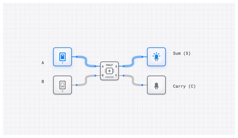
The XOR gate is the primary component of the HALF_ADDER. When you add two binary digits, the “Sum” is calculated using XOR, while the “Carry” is calculated using an AND gate.
Consider in binary.
- The Sum () is 0.
- The Carry () is 1.
- Result: (which is 2 in decimal).
Without the XOR gate, we would need a much more complex arrangement of gates just to perform basic addition. Every time your computer calculates a spreadsheet or renders a frame in a game, billions of XOR operations are happening every second inside the ALU_8BIT.
Explore the Half-Adder Template
Real-World Application 2: The Foundation of Cryptography
XOR is the “secret sauce” of symmetric encryption. It has a unique mathematical property: it is its own inverse.
If you have a message () and a secret key (), you can create a ciphertext () by XORing them together:
To get the original message back, you simply XOR the ciphertext with the same key:
This is the basis of the One-Time Pad, the only encryption method proven to be mathematically unbreakable (provided the key is truly random and used only once). Modern ciphers like AES (Advanced Encryption Standard) use XOR operations repeatedly in their “Round Key” addition steps. It’s fast, it’s efficient, and it’s incredibly secure.
Common Mistakes to Avoid
When building XOR circuits on digisim.io, keep these “Pro Tips” in mind:
- Floating Inputs: Never leave an XOR input unconnected. In a real circuit, a floating input can pick up electrical noise and cause the gate to oscillate. In digisim.io, use a CONSTANT_ZERO if you need to tie an unused input to a known state.
- Logic Levels: Remember that XOR is a logic gate, not a power switch. It can signal a difference, but it shouldn’t be used to drive high-current components directly without a BUFFER or a transistor model.
- The “OR” Confusion: Beginners often use an OR gate when they actually need an XOR. If your circuit needs to detect inequality (like a comparison in a sorting algorithm), the standard OR gate will fail you when both inputs are 1.
Master the Logic of Difference
A single rule — “output 1 if inputs differ” — underpins binary addition, error detection, and symmetric encryption. The next post in this series, The XNOR Gate, is the equality-detector counterpart, and XOR vs. XNOR: The Critical Difference in Error Detection compares them head-to-head.
Open the XOR component reference to verify the truth table, then build the controllable inverter from this post directly in the simulator.
Related Lessons for Further Study
- The XNOR Gate — the complement gate.
- The Half Adder and Half Adder vs. Full Adder — XOR as the sum bit.
- Visualizing Logic: Karnaugh Maps — minimization patterns that reduce to XOR.