ALU (4-bit)
Overview
- Purpose: The Arithmetic Logic Unit (ALU) is a digital circuit that performs arithmetic and logical operations on 4-bit binary numbers. It serves as the computational core of digital systems, executing various operations based on control signals.
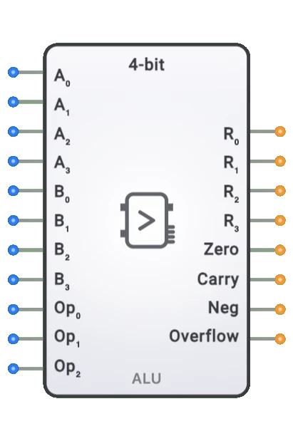
- Symbol: The ALU is represented by a rectangular block with inputs for two 4-bit operands (A and B) and operation selection, with outputs for the 4-bit result and status flags.
- DigiSim.io Role: The ALU enables computation in digital circuits, making it essential for implementing processors, calculators, and other computational systems.
Functional Description
Logic Behavior
The 4-bit ALU takes two 4-bit inputs, performs an operation selected by the operation control inputs, and produces a 4-bit result along with status flags. These flags indicate properties such as whether the result is zero, negative, or if there was a carry or overflow.
Operation Selection:
| Op Code | Operation | Description |
|---|---|---|
| 000 | Addition | R = A + B |
| 001 | Subtraction | R = A - B |
| 010 | Logical AND | R = A & B |
| 011 | Logical OR | R = A |
| 100 | Logical XOR | R = A ^ B |
| 101 | Logical NOT | R = ~A |
| 110 | Left Shift | R = A << 1 |
| 111 | Right Shift | R = A >> 1 |
Note: The exact operations and op codes may vary by implementation
Inputs and Outputs
Inputs:
- A[3:0]: 4-bit first operand.
- B[3:0]: 4-bit second operand.
- OpCode[2:0]: 3-bit operation select to determine which function to perform.
Outputs:
- Result[3:0]: 4-bit result of the operation.
- Zero Flag (Z): Set when the result is zero (all bits are 0).
- Carry Flag (C): Set when an operation produces a carry-out (for addition) or borrow (for subtraction).
- Negative Flag (N): Set when the most significant bit of the result is 1 (negative in two's complement).
- Overflow Flag (V): Set when a signed arithmetic operation results in an overflow.
Configurable Parameters
- Propagation Delay: The time delay between input changes and the corresponding output changes. This is simulated in DigiSim.io.
- Operation Set: Some implementations may have customizable operation sets or additional operations.
Visual Representation in DigiSim.io
The 4-bit ALU is displayed as a rectangular block with inputs on the left side and outputs on the right side. It's clearly labeled "ALU" to identify its function. Input pins (A[3:0], B[3:0], OpCode[2:0]) and output pins (Result[3:0], Z, C, N, V) are arranged in logical groups. The component visually indicates the current state of all inputs and outputs.
Educational Value
Key Concepts
- Binary Arithmetic: Demonstrates how computers perform basic arithmetic operations on binary numbers.
- Boolean Logic: Shows the implementation of logical operations on multi-bit values.
- Status Flags: Introduces the concept of condition codes that provide information about operation results.
- Computational Building Blocks: Illustrates how complex operations can be implemented using digital logic.
- Control Signals: Demonstrates how digital circuits can be configured to perform different functions.
Learning Objectives
- Understand how digital systems perform arithmetic and logical computations.
- Learn the relationship between binary operations and their results.
- Recognize how status flags provide essential information about operation outcomes.
- Apply ALU concepts to design simple computational systems.
- Comprehend how the ALU fits into the broader architecture of a computer system.
Usage Examples/Scenarios
- Simple CPU Design: The ALU forms the computational core of a CPU, executing arithmetic and logical operations.
- Calculator Circuits: Implementation of binary calculators that perform basic math operations.
- Data Manipulation: Processing data by performing bitwise operations for masking, filtering, or transforming values.
- Condition Testing: Using the ALU and its flags to test specific conditions in data values.
- Simple Controller: Create control systems that make decisions based on arithmetic comparisons.
Technical Notes
- The 4-bit ALU is typically constructed using a combination of adders, logic gates, and multiplexers to select between operations.
- The flags are derived from the operation result and carry chain, providing important information for control decisions.
- The ALU can be expanded to handle wider data (8-bit, 16-bit, etc.) by replicating the basic structure or using cascaded designs.
- For signed arithmetic, the 4-bit ALU can represent values from -8 to +7 using two's complement representation.
- In DigiSim.io, the ALU's behavior simulates real-world digital components, including propagation delays and flag generation.
Block Diagram
graph LR
    InputA[A 3:0] --> ALU[ALU<br/>Arithmetic Logic Unit]
    InputB[B 3:0] --> ALU
    OpCode[Operation Select<br/>OpCode 2:0] --> ALU
    ALU --> Result[Result 3:0]
    ALU --> Flags[Status Flags<br/>Z, C, N, V]
Characteristics
- Core component of a CPU's execution unit
- Performs both arithmetic and logical operations on binary data
- Uses control signals to select the desired operation
- Generates status flags that provide information about the result
- Can be cascaded to handle wider data words (8-bit, 16-bit, etc.)
- Utilizes carry propagation for multi-bit arithmetic
Applications
- Central processing unit (CPU) execution units
- Digital signal processing
- Address calculation in memory management
- Data manipulation in microcontrollers
- Graphics processing units
- Scientific calculators
- Digital control systems
- Embedded systems
Implementation
A 4-bit ALU can be constructed using:
- Full adders for arithmetic operations
- Logic gates for bitwise operations
- Multiplexers to select between different operations
- Decoders for operation selection
Functional Implementation
The 4-bit ALU contains:
- 4-bit adder/subtractor unit
- Logic unit for bitwise operations
- Shifter for shift operations
- Multiplexer to select the appropriate output
- Status flag logic
Related Components
- 8-bit ALU: Expanded version with 8-bit operands
- Register: Stores data before and after ALU operations
- Control Unit: Provides operation control signals to the ALU
- Adder: Specialized component for addition operations
- Comparator: Specialized component for comparison operations