Clock
Overview
- Purpose: The Clock is a digital component that generates a periodic signal alternating between HIGH and LOW states at a specified frequency. It provides the fundamental timing reference for synchronous digital systems.
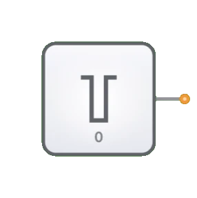
- Symbol: The Clock is represented by a rectangular block with a clock waveform symbol inside, having a single output pin.
- DigiSim.io Role: Serves as the timing source for simulated digital circuits, enabling all synchronous operations such as triggering flip-flops, coordinating data transfers, and synchronizing sequential logic.

Functional Description
Logic Behavior
The Clock produces a continuous square wave signal that oscillates between two logic states.
Waveform Characteristics:
- Square Wave: Alternates between HIGH (1) and LOW (0) states
- Period (T): Time for one complete cycle = 1/frequency
- Duty Cycle: Typically 50% (equal HIGH and LOW times)
- Rising Edge: Transition from LOW to HIGH (often triggers flip-flops)
- Falling Edge: Transition from HIGH to LOW (can also trigger components)
Signal States:
| Phase | Output Value |
|---|---|
| Low Phase | 0 (LOW) |
| High Phase | 1 (HIGH) |
Inputs and Outputs
- Inputs: None. The Clock is an autonomous signal generator with no logical inputs.
- Output: A single 1-bit output providing the clock signal.
Configurable Parameters
- Frequency: The rate at which the clock signal completes full cycles, measured in Hertz (Hz).
- Duty Cycle: The ratio of HIGH time to the total period, typically 50% in DigiSim.io.
- Initial State: The starting logic level of the clock output.
Visual Representation in DigiSim.io
The Clock is displayed as a rectangular block with an output pin on the right side. It typically includes a distinctive clock waveform symbol inside the block to identify its function. When connected in a circuit, the component visually indicates the current state of its output through color changes on the connecting wire, allowing users to observe the clock transitions during simulation.
Educational Value
Key Concepts
- Timing and Synchronization: Demonstrates how digital systems coordinate operations through a common timing reference.
- Signal Generation: Illustrates the concept of a periodic digital signal with predictable transitions.
- Sequential Logic Control: Shows how clock signals trigger state changes in sequential circuits.
- System Speed: Introduces the relationship between clock frequency and system operation speed.
Learning Objectives
- Understand the role of clock signals in synchronizing digital systems.
- Learn how clock frequency determines the operating speed of digital circuits.
- Recognize how sequential components like flip-flops and registers use clock signals.
- Apply clock signals appropriately in various digital circuit designs.
- Comprehend the importance of timing in digital systems.
Usage Examples/Scenarios
- Sequential Logic Circuits: Triggering state changes in flip-flops, registers, and counters.
- CPU/Processor Timing: Coordinating instruction execution in processor designs.
- Data Transfer: Synchronizing data movement between memory and processing elements.
- Digital Signal Timing: Providing precise timing intervals for signal processing.
- State Machine Control: Advancing state machines through their sequence of states.
Technical Notes
- Unlike combinational logic, which responds immediately to input changes, clock-driven sequential logic changes state only on specific clock transitions.
- In DigiSim.io, the Clock component runs at a speed suitable for visual observation of circuit behavior, which is much slower than actual digital hardware.
- Multiple clock sources with different frequencies can be used in more complex designs where different timing domains are required.
- When designing sequential circuits, proper attention must be paid to setup and hold times relative to clock edges.
Characteristics
- Generates a continuous square wave signal
- Defined by frequency (cycles per second, measured in Hertz)
- Has duty cycle (ratio of HIGH time to total period)
- Provides timing synchronization for digital components
- Essential for sequential logic operations
- No logic inputs, only an output
Parameters
- Frequency: How rapidly the clock signal oscillates (e.g., 1 Hz, 1 MHz)
- Duty Cycle: Percentage of time the signal is HIGH in each cycle (typically 50%)
- Phase: Timing relationship with other clock signals
- Rise/Fall Times: How quickly the signal transitions between states
Applications
- Synchronizing sequential logic circuits
- Triggering state changes in flip-flops and registers
- Providing timing reference for CPUs and microcontrollers
- Controlling data transfer in memory systems
- Setting operating speed for digital systems
- Synchronizing communication between different components
- Generating timing signals for counters and timers
Implementation
In hardware implementations, clocks are generated using:
- Crystal oscillators for precise frequency control
- RC (resistor-capacitor) oscillators for simpler applications
- Phase-locked loops (PLLs) for frequency synthesis
- Clock distribution networks to ensure synchronous operation across a circuit
Related Components
- Input Switch: Provides manual signal control, unlike the automatic Clock
- Oscillator: The underlying component that generates the Clock signal
- Counter: Often used with clocks for frequency division
- PLL (Phase-Locked Loop): Used to generate clock signals at various frequencies