XOR Gate
Overview
- Purpose: The XOR (Exclusive OR) gate performs a logical operation that outputs HIGH (logical '1') when an odd number of inputs are HIGH. For a two-input XOR gate, the output is HIGH when exactly one input is HIGH.
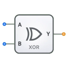
- Symbol: The XOR gate is represented by a symbol with a double curved line on the input side, distinguishing it from the regular OR gate.
- DigiSim.io Role: Serves as a fundamental component for building arithmetic circuits, comparators, and error detection systems.
Functional Description
Logic Behavior
The XOR gate implements exclusive disjunction, producing a HIGH output when an odd number of its inputs are HIGH.
Truth Table (for a 2-input XOR gate):
| Input A | Input B | Output Y |
|---|---|---|
| 0 | 0 | 0 |
| 0 | 1 | 1 |
| 1 | 0 | 1 |
| 1 | 1 | 0 |
Boolean Expression: Y = A ⊕ B (Y equals A XOR B)
Inputs and Outputs
- Inputs: The XOR gate has 2 inputs (A, B).
- Output: A single 1-bit output representing the result of the XOR operation.
Visual Representation in DigiSim.io
The XOR gate is displayed with input pins on the left side and an output pin on the right side. Its symbol includes a distinctive double curved line on the input side, which distinguishes it from the OR gate. When connected in a circuit, the component visually indicates the logic state of its pins through color changes on connecting wires.
Educational Value
Key Concepts
- Boolean Algebra: Demonstrates the exclusive OR operation as a distinct Boolean function.
- Combinational Logic: Shows how a gate's output is determined solely by the current input values.
- Bit Comparison: Illustrates the concept of detecting when bits are different.
- Arithmetic Operations: Introduces how XOR can be used in binary addition circuits.
Learning Objectives
- Understand the exclusive OR operation and its truth table representation.
- Learn the difference between inclusive OR (OR gate) and exclusive OR (XOR gate).
- Recognize how XOR gates are used in arithmetic circuits, particularly for binary addition.
- Apply XOR gates in parity generation/checking for error detection systems.
Usage Examples/Scenarios
- Binary Addition: In half-adder circuits, an XOR gate generates the sum bit of two binary inputs.
- Parity Generation/Checking: Creating or verifying parity bits in data transmission for error detection.
- Bit Comparators: Detecting when corresponding bits are different in two binary numbers.
- Controlled Inverters: Using an XOR gate with one control input to selectively invert a signal.
Technical Notes
- The XOR gate's output exhibits high impedance (high-Z) if any of its inputs are in a high-Z state or undefined.
- While a basic logic gate in DigiSim.io, XOR gates are typically implemented using combinations of AND, OR, and NOT gates in physical circuits.
- For multi-input XOR gates, the output is HIGH if and only if an odd number of inputs are HIGH, making it useful for parity calculations.
- Propagation delay is generally higher than basic gates due to the more complex internal structure. Typical 74HC CMOS values are around 10–17 ns at 5 V; 74LS TTL values are around 14–23 ns.
Transistor-Level Implementation
- CMOS: Uses complementary pairs of MOSFETs
- TTL: Uses bipolar junction transistors
Integrated Circuits
- 74xx86: Quad 2-input XOR gates
- 74xx266: Quad 2-input XNOR gates
Transmission Gate Implementation
- Uses complementary pass transistors
- Efficient for certain applications
Circuit Implementation (2-Input XOR Using Basic Gates)
graph LR
    A[Input A] --> NOT1[NOT Gate]
    B[Input B] --> NOT2[NOT Gate]

    NOT1 --> AND1[AND Gate]
    B --> AND1

    A --> AND2[AND Gate]
    NOT2 --> AND2

    AND1 --> OR[OR Gate]
    AND2 --> OR
    OR --> Y[Output Y]
Logic: Y = A·B̄ + Ā·B (A XOR B produces HIGH when inputs differ)
Boolean Equations
For a 2-input XOR gate:
- Y = A ⊕ B
- Y = A·B̄ + Ā·B
- Y = (A + B) · (Ā + B̄)
- Y = A ≠ B (inequality)
For a 3-input XOR gate:
- Y = A ⊕ B ⊕ C
- Y = A·B̄·C̄ + Ā·B·C̄ + Ā·B̄·C + A·B·C
Related Components
- OR Gate: Outputs true if any input is true
- AND Gate: Outputs true only if all inputs are true
- XNOR Gate: Complement of XOR, outputs true when inputs are equal
- Half Adder: Combines XOR and AND gates for binary addition
- Full Adder: Uses XOR gates for sum generation
- Parity Generator/Checker: Uses XOR gates for error detection
- Multiplexers: Can implement XOR functionality with proper configuration
- Controlled Inverters: Similar functionality in specific applications