Multiplexer
Overview
- Purpose: The Multiplexer (MUX) is a digital component that selects one of several input signals and forwards it to a single output line. It functions as a digitally controlled switch that routes one of multiple input data lines to the output.
- Symbol: The Multiplexer is represented by a rectangular block with two data inputs (D0, D1), a select input (Sel), and a single output (Y).
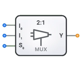
- DigiSim.io Role: The DigiSim.io Multiplexer is a 2-to-1 (2:1) MUX that selects between two data inputs based on a single select line, serving as a fundamental data selection component in digital circuits.
Functional Description
Logic Behavior
The DigiSim.io Multiplexer is a 2-to-1 MUX. It uses a single select input (Sel) to determine which of the two data inputs (D0 or D1) is forwarded to the output (Y). When Sel=0, the output Y equals D0. When Sel=1, the output Y equals D1.
Truth Table (2-to-1 Multiplexer):
| Sel | D0 | D1 | Y |
|---|---|---|---|
| 0 | 0 | X | 0 |
| 0 | 1 | X | 1 |
| 1 | X | 0 | 0 |
| 1 | X | 1 | 1 |
Inputs and Outputs
Inputs (3 total):
- D0 (Data 0): 1-bit data input, selected when Sel=0.
- D1 (Data 1): 1-bit data input, selected when Sel=1.
- Sel (Select): 1-bit control input that determines which data input (D0 or D1) appears at the output.
Output (1 total):
- Y (Output): 1-bit output that reflects the value of the selected data input.
Configurable Parameters
- Propagation Delay: The time it takes for the output to change after a select or input change.
Visual Representation in DigiSim.io
The Multiplexer is displayed as a rectangular block with the two data inputs (D0, D1) on one side and the select input (Sel) typically at the bottom. The output (Y) is on the opposite side. When connected in a circuit, the component visually indicates the active data path and logic states through color changes on connecting wires.
Educational Value
Key Concepts
- Data Selection: Demonstrates the concept of choosing one signal from multiple options.
- Digital Switching: Illustrates how digital systems route data dynamically.
- Binary Encoding: Shows how binary select values correspond to specific data paths.
- Combinational Logic: Introduces how complex logic functions can be implemented using multiplexers.
Learning Objectives
- Understand how multiplexers direct the flow of data in digital systems.
- Learn how binary select codes determine which input is routed to the output.
- Recognize the role of multiplexers in creating larger digital systems.
- Apply multiplexers to implement various combinational logic functions.
- Comprehend how multiplexers can reduce component count in certain circuit designs.
Usage Examples/Scenarios
- Data Selection: Selecting one of multiple data sources to be processed.
- Bus Systems: Controlling which device gets access to a shared data bus.
- Logic Implementation: Implementing any combinational logic function by using a multiplexer with constants and variables as inputs.
- Parallel-to-Serial Conversion: Selecting bits sequentially from a parallel input.
- Memory Systems: Addressing and selecting specific memory cells or words.
Technical Notes
- The number of select lines (S) and the number of data inputs (I) have a relationship: 2^S = I. For example, the DigiSim.io 2-to-1 multiplexer uses 1 select line to choose between 2 data inputs.
- Cascading multiple multiplexers allows the creation of larger multiplexers. For example, two 4:1 multiplexers and one 2:1 multiplexer can create an 8:1 multiplexer.
- Multiplexers can be combined with demultiplexers to create bidirectional data routing systems.
- In physical implementations, multiplexers may experience brief output glitches during select line transitions.
Characteristics
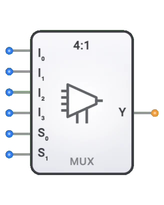
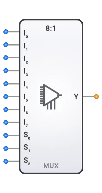
- Channel Count: Described as N:1 (e.g., 2:1, 4:1, 8:1, 16:1)
- Select Lines: log₂(N) select inputs to choose among N data inputs
- Propagation Delay: Time between input change and stable output
- Fan-Out: Number of logic gates it can drive
- Power Consumption: Typically increases with channel count
- Enable Control: Some multiplexers include an enable input
- Data Width: Can be 1-bit or multi-bit (bus multiplexers)
- Glitch Immunity: Quality of avoiding transient incorrect outputs during transitions
Types of Multiplexers
Binary Multiplexers
- 2:1 (1 select line)
- 4:1 (2 select lines)
- 8:1 (3 select lines)
- 16:1 (4 select lines)
Bus Multiplexers
- Handle multiple bits in parallel
- Common widths: 4-bit, 8-bit, 16-bit, 32-bit
Analog Multiplexers
- Switch analog signals
- Maintain signal integrity with low resistance when on
Tree Multiplexers
- Constructed by cascading smaller multiplexers
- Used for large-scale implementations
Bidirectional Multiplexers
- Allow signal flow in either direction
- Used in bidirectional buses
Applications
Data Selection and Routing
- Selecting between multiple data sources
- Memory address multiplexing in DRAM
- Bus arbitration in computer systems
Communication Systems
- Time-division multiplexing (TDM) for channel sharing
- Line selection in telecommunications
- Network switching applications
Logic Implementation
- Implementing boolean functions
- Look-up tables (LUTs) in FPGAs
- Programmable logic arrays
Testing and Debugging
- Signal probing and monitoring
- Test point selection
- Diagnostic signal routing
Arithmetic Circuits
- ALU function selection
- Conditional operations
- Bit manipulation functions
Control Systems
- Operation mode selection
- Signal path configuration
- State machine implementations
Implementation
Multiplexers can be implemented using:
Basic Logic Gates
- AND, OR, and NOT gates
- Transmission gates
Integrated Circuits
- 74xx series:
- 74157: Quad 2:1 multiplexer
- 74153: Dual 4:1 multiplexer
- 74151: 8:1 multiplexer
- 74150: 16:1 multiplexer
- 74xx series:
Transistor-Level
- CMOS pass transistors
- Transmission gates
- Tri-state buffers
HDL Designs (Verilog/VHDL)
- Case statements
- Conditional assignments
- Parameterized designs
Circuit Implementation (2:1 MUX)
A basic 2:1 multiplexer can be implemented using basic logic gates:
AND-OR Gate Implementation
graph LR
    Input0[Input I0] --> AndGate0[AND Gate]
    SelectS[Select S] --> NotGate[NOT Gate]
    NotGate --> AndGate0

    Input1[Input I1] --> AndGate1[AND Gate]
    SelectS --> AndGate1

    AndGate0 --> OrGate[OR Gate]
    AndGate1 --> OrGate
    OrGate --> OutputY[Output]
Transmission Gate Implementation
graph LR
    Input0[Input I0] --> TransGate0[Transmission Gate 0]
    Input1[Input I1] --> TransGate1[Transmission Gate 1]

    TransGate0 --> OutputY[Output]
    TransGate1 --> OutputY

    SelectS[Select S] --> TransGate1
    SelectS --> NotGate[NOT Gate]
    NotGate --> TransGate0
Related Components
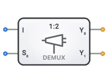
- Demultiplexers: Perform the reverse operation (1-to-N routing)
- Encoders: Convert multiple input lines to binary code
- Decoders: Convert binary code to multiple output lines
- Bus Transceivers: Bidirectional data transfer with direction control
- Selectors: Similar to multiplexers but with different control logic
- Crossbar Switches: Grid of multiplexers for flexible interconnection
- Priority Encoders: Selects highest priority input
- Digital Switches: Electronic equivalents of mechanical switches
- Multiplexer Trees: Cascaded multiplexers for large input counts
- Programmable Logic Arrays: Use multiplexers as building blocks