8-bit Comparator
Overview
- Purpose: The 8-bit Comparator is a digital circuit that compares two 8-bit binary numbers (A and B) and determines their relative magnitude, generating output signals that indicate whether A equals B, is greater than B, or is less than B.
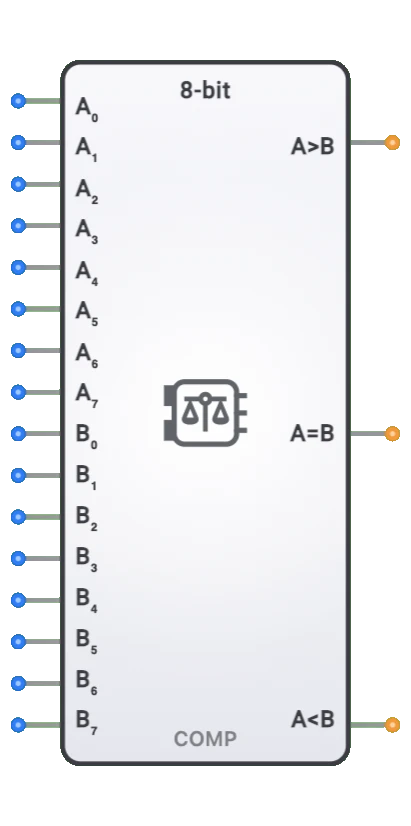
- Symbol: Represented as a rectangular block with two 8-bit inputs for the numbers being compared (A[7:0] and B[7:0]) and three outputs indicating the comparison result (A=B, A>B, A<B).
- DigiSim.io Role: Serves as a fundamental decision-making component in digital circuits, enabling value comparison operations essential for implementing conditional logic, sorting networks, and control systems.
Functional Description
Logic Behavior
The 8-bit Comparator examines two 8-bit binary inputs and determines their relationship, asserting the appropriate output line to indicate whether the first input is equal to, greater than, or less than the second input.
Truth Table:
| Comparison Condition | A=B Output | A>B Output | A<B Output |
|---|---|---|---|
| A = B | 1 | 0 | 0 |
| A > B | 0 | 1 | 0 |
| A < B | 0 | 0 | 1 |
Note: The comparison is made based on the binary value of inputs A[7:0] and B[7:0], where A7/B7 are the most significant bits.
Inputs and Outputs
Inputs:
- A[7:0]: 8-bit first operand for comparison.
- B[7:0]: 8-bit second operand for comparison.
- Some implementations may include additional control inputs like enable (EN) or cascading inputs for building larger comparators.
Outputs:
- Equal (A=B): 1-bit output that is HIGH when A equals B.
- Greater (A>B): 1-bit output that is HIGH when A is greater than B.
- Less (A<B): 1-bit output that is HIGH when A is less than B.
Configurable Parameters
- Comparison Mode: Whether the comparison is for unsigned binary numbers or signed (two's complement) numbers.
- Output Logic: Whether outputs are active-high or active-low.
- Propagation Delay: The time it takes for outputs to change after input changes.
- Cascading Configuration: Whether the comparator can be cascaded to compare larger numbers.
Visual Representation in DigiSim.io
The 8-bit Comparator is displayed as a rectangular block with labeled inputs on the left side (A[7:0], B[7:0]) and outputs (A=B, A>B, A<B) on the right side. When connected in a circuit, the component visually indicates the comparison result through the values shown on its outputs and color changes on connecting wires.
Educational Value
Key Concepts
- Binary Comparison: Demonstrates how digital circuits determine the relationship between binary numbers.
- Decision Making: Illustrates how computers make comparisons that drive conditional operations.
- Magnitude Determination: Shows how the relative size of binary values is established in digital systems.
- Combinational Logic: Presents a practical application of combinational circuits with multiple outputs.
- Sequential Logic Control: Introduces how comparison results can control the flow of operations in sequential circuits.
Learning Objectives
- Understand how digital systems compare numeric values.
- Learn the implementation of comparison operations using logic gates.
- Recognize how comparison results drive decision-making in digital systems.
- Apply comparator concepts to design selection circuits, min/max finders, and range detectors.
- Comprehend the difference between unsigned and signed number comparison.
Usage Examples/Scenarios
- Conditional Branching: Determining whether to take a branch in a CPU based on comparing register values.
- Sorting Networks: Building blocks for arranging data in ascending or descending order.
- Limit Detection: Identifying when a value exceeds or falls below specific thresholds.
- Address Comparison: Determining when a memory address matches a specific value for decoding.
- Window Comparison: Detecting when a value falls within a specific range.
- Zero Detection: Identifying when a calculation result equals zero.
- Control Systems: Comparing setpoints to actual values in feedback control loops.
Technical Notes
- The 8-bit comparator can be implemented using a hierarchical approach, comparing from most significant to least significant bits.
- For unsigned numbers, the comparison is straightforward, but signed numbers require special handling of the most significant bit.
- Propagation delay increases with the number of bits due to the ripple nature of most comparator implementations.
- Cascading comparators allows comparing numbers wider than 8 bits, at the cost of increased delay.
- In high-speed systems, look-ahead techniques similar to those in adders can be implemented to reduce comparison delay.
- In DigiSim.io, the comparator behavior models real-world digital components with proper handling of multi-bit inputs.
Characteristics
Input Configuration:
- Two 8-bit binary inputs (A[7:0] and B[7:0])
- Each input represents a binary number (0-255)
- Typically accepts standard digital logic levels
- May include cascading inputs in expandable designs
- Input loading consistent with logic family
- May include additional control inputs in some implementations
Output Configuration:
- Three primary outputs indicating comparison result:
- Equal (A=B): High when all corresponding bits match
- Greater Than (A>B): High when A is numerically larger than B
- Less Than (A<B): High when A is numerically smaller than B
- Outputs typically provide standard logic levels
- May include open-collector/open-drain options for wired-OR configurations
- Capable of driving standard digital loads
- Some implementations may provide complementary outputs
- Three primary outputs indicating comparison result:
Functionality:
- Performs simultaneous comparison of two 8-bit numbers
- Evaluates both magnitude and equality in a single operation
- Binary comparison treats inputs as unsigned numbers by default
- Signed comparison available in specialized implementations
- Cascadable for comparing wider numbers
- Output states are mutually exclusive (only one active at a time)
- Combinational logic implementation (no clock required)
Propagation Delay:
- Input-to-output: 15-35ns typical
- Delay increases with bit width due to carry propagation
- Critical path typically through the A>B and A<B determination
- Equality detection generally faster than inequality
- Technology dependent (TTL, CMOS, etc.)
- Temperature and voltage variation affects timing
- Cascaded designs have accumulated delay
Fan-Out:
- Typically drives 10-20 standard loads
- Output loading affects propagation delay
- May require buffering for high fan-out applications
- Consistent with the logic family used
Power Consumption:
- Static power minimal in CMOS implementations
- Dynamic power proportional to switching activity
- Power consumption increases with operating frequency
- Moderate complexity results in moderate power needs
- Technology dependent (CMOS lowest static power)
- Power increases with additional features
Circuit Complexity:
- Moderate complexity
- Requires extensive logic for bit-by-bit comparison
- Implementation complexity increases with bit width
- Additional complexity for cascading capability
- Magnitude comparison more complex than equality testing
- Integrated implementations reduce external component count
Implementation Methods
Gate-Level Implementation
- Built from basic logic gates (AND, OR, NOT, XOR)
- Separate circuits for equality and magnitude comparison
- XOR gates typically used for equality detection
- Cascaded logic for magnitude comparison
- Conceptually straightforward but requires many gates
- Educational implementation demonstrates comparison principles
Magnitude Comparison Logic
- Uses cascaded decision logic from MSB to LSB
- Prioritizes higher-order bit differences
- Decision tree implementation
- Each bit comparison depends on higher bit results
- More efficient than bit-by-bit full comparison
- Common in custom logic implementations
Integrated Circuit Implementation
- Dedicated comparator ICs
- Examples: 74HC85 (4-bit, cascadable), 74HC688 (8-bit equality)
- Various features: cascading inputs/outputs, equality-only versions
- Available in different logic families (TTL, CMOS, etc.)
- Reduced component count and board space
- Well-defined timing characteristics
Cascaded 4-bit Comparators
- Two 4-bit comparators combined with control logic
- Commercially available 4-bit comparators used as building blocks
- Additional logic for combining results
- Smaller comparators comparing upper and lower nibbles
- Results combined based on significance
- Cost-effective approach using standard components
Subtractor-Based Implementation
- Subtract B from A using a binary subtractor
- Sign and zero flags from result determine relationship
- Efficient when subtractor is already available
- Similar to how CPUs perform comparisons
- Dual-purpose implementation shares arithmetic hardware
- Common in ALU designs
FPGA/ASIC Implementation
- Implemented using optimized LUT structures
- Takes advantage of fast carry chains in FPGAs
- Can be optimized for speed or area
- Potentially lower delay than discrete implementations
- Often synthesized from HDL descriptions
- Resource-efficient in modern programmable logic
Specialized Comparators
- Signed comparators for two's complement numbers
- Magnitude-only comparators for absolute value comparison
- Window comparators to test if within a range
- Threshold comparators with programmable reference
- Fuzzy comparators with tolerance bands
- Application-specific optimizations
Applications
Arithmetic and Logic Operations
- Conditional branching in CPUs
- Result evaluation in ALUs
- Overflow/underflow detection
- Range checking for operations
- Boundary condition testing
- Decision logic for mathematical operations
Data Sorting and Searching
- Comparison element in sorting networks
- Binary search implementations
- Database query operations
- Priority encoders and arbiters
- Maximum/minimum value detection
- Median filters
Control Systems
- Set point comparison in control loops
- Limit checking and boundary detection
- Threshold crossing detection
- Error magnitude evaluation
- Safety interlock conditions
- Process control decision making
Digital Signal Processing
- Amplitude threshold detection
- Peak detection algorithms
- Signal level comparison
- Pattern matching
- Adaptive filter control
- Range verification for signal values
Memory and I/O Systems
- Address decoding and range checking
- Memory address comparison
- Memory management unit functions
- Cache tag comparison
- I/O port address recognition
- DMA boundary checking
User Interface and Displays
- Input validation
- Range checking for user inputs
- Threshold detection for analog inputs
- Bar graph level determination
- Alarm limit detection
- User selection comparison
Testing and Verification
- Expected vs. actual result comparison
- Boundary scan testing
- Tolerance checking
- Pass/fail determination
- Calibration verification
- Functional testing of digital systems
Limitations
Propagation Delay
- Significant delay for wide comparisons
- Carry propagation limitations at high speeds
- Cascading increases delay proportionally
- Critical timing path in high-speed systems
- Delay variations with temperature and voltage
- May limit system performance in time-critical applications
Size and Width Constraints
- Fixed 8-bit width requires cascading for wider comparisons
- Cascading complexity increases with width
- Additional logic needed for cascading
- Performance degradation when cascaded
- Interconnect complexity in multi-chip solutions
- Dedicated wider comparators may be more efficient
Unsigned vs. Signed Comparison
- Standard comparators assume unsigned numbers
- Special consideration needed for signed comparisons
- Different logic required for two's complement comparison
- Sign bit handling adds complexity
- May require different implementations for different number types
- Universal comparators more complex
Noise Sensitivity
- Simultaneous transitions on multiple inputs can cause glitches
- Result momentarily invalid during input changes
- May require input synchronization in noisy environments
- Metastability issues when used with asynchronous inputs
- Critical in safety applications
- May require filtering or hysteresis
Implementation Trade-offs
- Speed vs. area trade-offs in design
- Power consumption increases with faster implementations
- Higher precision requires more resources
- Cascading vs. monolithic implementation decisions
- Technology selection impacts capabilities
- Cost/complexity balance considerations
Circuit Implementation Detail
8-bit Equality Comparator
graph LR
    A0[A0] --> XOR0[XOR]
    B0[B0] --> XOR0

    A1[A1] --> XOR1[XOR]
    B1[B1] --> XOR1

    A2[A2] --> XOR2[XOR]
    B2[B2] --> XOR2

    A7[A7] --> XOR7[XOR]
    B7[B7] --> XOR7

    XOR0 --> NOR[NOR Gate]
    XOR1 --> NOR
    XOR2 --> NOR
    XOR7 --> NOR

    NOR --> EQ[A=B Output]
Logic: XOR outputs 0 when bits match, NOR outputs 1 when all XORs are 0 (all bits equal).
74HC688 8-bit Equality Comparator
Pin Configuration:
| Pin Group | Pins | Function |
|---|---|---|
| A Inputs | P0-P7 | 8-bit input A |
| B Inputs | Q0-Q7 | 8-bit input B |
| Enable | /E | Active-LOW enable |
| Output | P=Q | Active-LOW equality output |
| Power | VCC, GND | +5V and Ground |
Operation:
- P=Q = LOW: When /E=LOW AND all bits match (P0=Q0, P1=Q1, ..., P7=Q7)
- P=Q = HIGH: When disabled (/E=HIGH) OR any bit differs
- Use Case: Fast byte comparison, address decoding
Cascaded 74HC85 4-bit Magnitude Comparators
Cascade Configuration for 8-bit Comparison:
graph LR
    A47[A4-A7<br/>Lower 4 bits] --> CMP1[74HC85<br/>Comparator 1]
    B47[B4-B7<br/>Lower 4 bits] --> CMP1

    A03[A0-A3<br/>Upper 4 bits] --> CMP2[74HC85<br/>Comparator 2]
    B03[B0-B3<br/>Upper 4 bits] --> CMP2

    CMP1 -->|A>B| CMP2
    CMP1 -->|A=B| CMP2
    CMP1 -->|A<B| CMP2

    CMP2 --> OUT[Final Outputs<br/>A>B, A=B, A<B]
Cascade Connection:
| Comparator | Inputs | Cascade Inputs | Function |
|---|---|---|---|
| CMP1 (MSB) | A4-A7, B4-B7 | IA>B=1, IA=B=1, IA<B=0 | Compare upper 4 bits |
| CMP2 (LSB) | A0-A3, B0-B3 | From CMP1 outputs | Compare lower 4 bits |
Operation: MSB comparator result cascades to LSB comparator for final decision.
Related Components
- 4-bit Comparator: Smaller version for nibble-sized comparisons
- 16-bit Comparator: Extended version for word-sized comparisons
- Magnitude Comparator: Determines only greater/less relationship
- Equality Comparator: Tests only for equality between inputs
- Window Comparator: Tests if a value is within a specified range
- Digital Subtractor: Can be used to implement comparison functions
- ALU (Arithmetic Logic Unit): Often includes comparison operations
- Priority Encoder: Determines highest priority active input
- Digital Multiplexer: Often controlled by comparator outputs
- Zero Detector: Specialized equality comparator testing for zero