Encoder
Overview
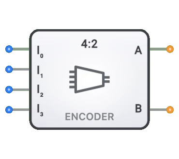
- Purpose: The Encoder is a 4-to-2 priority encoder — a combinational digital circuit that converts active input signals into a binary code representing the highest-priority active input. It performs the reverse operation of a decoder, reducing 4 input lines to a 2-bit binary code.
- Symbol: The Encoder is represented by a rectangular block with 4 input lines (D0, D1, D2, D3) and 2 output lines (Q0, Q1).
- DigiSim.io Role: Serves as a fundamental building block for priority detection, address generation, and input encoding in digital circuits.
Functional Description
Logic Behavior
The Encoder is a priority encoder that outputs the binary code of the highest-priority active input. When multiple inputs are active simultaneously, the encoder outputs the code for the highest-numbered active input — lower-priority inputs are treated as don't-cares (X).
Truth Table (4-to-2 Priority Encoder):
| D3 | D2 | D1 | D0 | Q1 | Q0 |
|---|---|---|---|---|---|
| 0 | 0 | 0 | 1 | 0 | 0 |
| 0 | 0 | 1 | X | 0 | 1 |
| 0 | 1 | X | X | 1 | 0 |
| 1 | X | X | X | 1 | 1 |
Inputs and Outputs
Inputs:
- 4 Data Inputs (D0, D1, D2, D3): Four input lines, where D3 has the highest priority and D0 has the lowest.
Outputs:
- 2 Binary Outputs (Q0, Q1): 2-bit binary code representing the highest-priority active input.
Configurable Parameters
- Priority Handling: The encoder uses priority resolution — when multiple inputs are active, the highest-numbered input takes precedence.
- Propagation Delay: The time it takes for outputs to change after input changes.
Visual Representation in DigiSim.io
The Encoder is displayed as a rectangular block with 4 input pins (D0–D3) on one side and 2 output pins (Q0, Q1) on the opposite side. When connected in a circuit, the component visually indicates active inputs and the resulting binary code on outputs through color changes on connecting wires.
Educational Value
Key Concepts
- Binary Encoding: Demonstrates how multiple signals can be encoded into compact binary form.
- Data Compression: Illustrates how multiple signal lines can be reduced to fewer lines.
- One-Hot to Binary Conversion: Shows the relationship between one-hot and binary representations.
- Combinational Logic Design: Introduces the design of logic circuits for encoding functions.
Learning Objectives
- Understand how multiple input signals can be encoded into a binary format.
- Learn the relationship between encoders and decoders as complementary components.
- Recognize the difference between basic encoders and priority encoders.
- Apply encoders in designing input processing systems and address generators.
- Comprehend how encoders can efficiently reduce the number of signal lines in digital systems.
Usage Examples/Scenarios
- Keypad Encoding: Converting keypad button presses into binary codes.
- Priority Detection: Identifying the highest-priority active input in systems with priority requirements.
- Address Generation: Creating binary addresses from one-hot selection signals.
- Input Processing: Converting various input formats into standardized binary codes.
- Control Systems: Encoding multiple status signals into compact form for processing.
Technical Notes
- The DigiSim.io encoder is a priority encoder: when multiple inputs are active, it outputs the binary code of the highest-priority (highest-numbered) active input.
- The 4-to-2 configuration uses 4 inputs (D0–D3) and produces a 2-bit binary output (Q0, Q1).
- In DigiSim.io, the encoder responds immediately to input changes, modeling the combinational logic behavior of priority encoders.
Characteristics
- Input Size: 4 input lines (D0–D3)
- Output Size: 2 output lines (Q0, Q1)
- Propagation Delay: Time delay between input change and stable output
- Fan-In: Number of input lines the encoder can handle
- Fan-Out: Number of logic gates each output can drive
- Input Validation: Optional feature to detect valid/invalid inputs
- Enable Control: Some encoders include enable inputs to control operation
- Input Priority: Whether the encoder respects priority among inputs
- Power Consumption: Energy usage during operation
Types of Encoders
Basic Encoders
- Simple encoder with no priority or validation features
- Assumes only one input is active at a time
Priority Encoders
- Resolves multiple active inputs based on priority
- Outputs the code for the highest priority input
- Often includes a "valid input" output flag
Decimal-to-BCD Encoders
- 10-to-4 encoders for decimal to binary-coded decimal conversion
- Used in numeric display and keypad applications
Octal-to-Binary Encoders
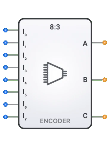
- 8-to-3 encoders for octal to binary conversion
- Common in computing systems
Hexadecimal-to-Binary Encoders
- 16-to-4 encoders for hexadecimal to binary conversion
- Used in address decoding applications
Keyboard Encoders
- Specialized encoders for keypad or keyboard inputs
- Convert key presses to binary codes
Applications
Address Generation
- Converting one-hot signals to binary addresses
- Memory addressing in digital systems
Input Peripherals
- Keyboard and keypad input encoding
- Switch array to binary conversion
Instruction Decoding
- Encoding instruction patterns in CPUs
- Opcode generation
Control Systems
- Status encoding for control applications
- Mode selection encoding
Digital Multiplexing
- Address selection for multiplexer control
- Channel selection in communication systems
Data Compression
- Reducing multiple signal lines to fewer lines
- Converting parallel data to more compact formats
Implementation Methods
Logic Gate Arrays
- Using OR gates to combine inputs based on output bit patterns
- Can be implemented with discrete components or in IC form
Integrated Circuits
- 74148: 8-to-3 priority encoder
- 74147: 10-to-4 decimal to BCD priority encoder
- 74LS348: 8-to-3 priority encoder with enable
HDL Design
- Case statements or conditional assignments
- Priority if-else chains for priority encoders
- Easily parameterized for different sizes
ROM-Based Implementation
- Using look-up tables stored in ROM
- Suitable for complex encoding schemes
Circuit Implementation (4-to-2 Priority Encoder)
A 4-to-2 priority encoder can be implemented using OR gates with priority logic:
graph LR
    D1[D1] --> OR0[OR Gate]
    D3[D3] --> OR0
    OR0 --> Q0[Q0 Output]

    D2[D2] --> OR1[OR Gate]
    D3 --> OR1
    OR1 --> Q1[Q1 Output]
Logic: Q0 is HIGH when D1 or D3 is the highest-priority active input. Q1 is HIGH when D2 or D3 is the highest-priority active input.
Boolean Equations (4-to-2 Priority Encoder)
For the 4-to-2 priority encoder:
Q0 = D1·D̄2·D̄3 + D3
Q1 = D2·D̄3 + D3
Simplified (priority logic ensures highest-numbered active input wins):
Q0 = D3 + D1·D̄2
Q1 = D3 + D2
Where + represents logical OR, · represents logical AND, and D̄ represents NOT
Related Components
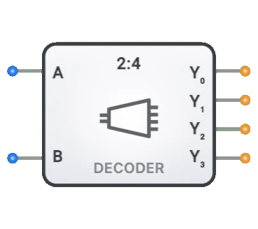
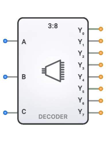
- Decoders: Perform the inverse operation (binary to one-hot)
- Multiplexers: Used with encoders for data selection
- Demultiplexers: Used with decoders for data distribution
- Priority Arbiters: Similar to priority encoders but with different output format
- Code Converters: Transform between different encoding schemes
- Binary Counters: Often use encoders for state detection
- Comparators: Sometimes implemented using encoder principles
- Address Decoders: Inverse operation used in memory systems