Digit Display
Overview
- Purpose: The Digit Display is an output device that converts 4-bit binary or Binary-Coded Decimal (BCD) input into a visual numerical representation, displaying decimal digits (0-9) or hexadecimal characters (0-F).
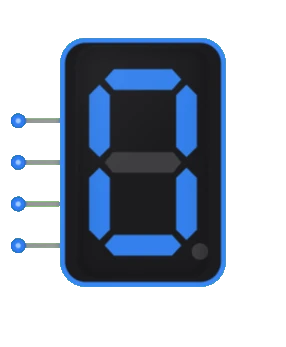
- Symbol: Typically represented as a rectangular block with 4 input lines and a 7-segment display visual output.
- DigiSim.io Role: Serves as a vital human interface component in digital circuits, allowing users to visualize numeric values, calculation results, or counter outputs.
Functional Description
Logic Behavior
The Digit Display decodes a 4-bit input value and drives the appropriate segments of a 7-segment display to visually represent the corresponding digit or character.
Input/Output Table:
| Input D | Input C | Input B | Input A | Displayed Digit |
|---|---|---|---|---|
| 0 | 0 | 0 | 0 | 0 |
| 0 | 0 | 0 | 1 | 1 |
| 0 | 0 | 1 | 0 | 2 |
| 0 | 0 | 1 | 1 | 3 |
| 0 | 1 | 0 | 0 | 4 |
| 0 | 1 | 0 | 1 | 5 |
| 0 | 1 | 1 | 0 | 6 |
| 0 | 1 | 1 | 1 | 7 |
| 1 | 0 | 0 | 0 | 8 |
| 1 | 0 | 0 | 1 | 9 |
| 1 | 0 | 1 | 0 | A |
| 1 | 0 | 1 | 1 | B |
| 1 | 1 | 0 | 0 | C |
| 1 | 1 | 0 | 1 | D |
| 1 | 1 | 1 | 0 | E |
| 1 | 1 | 1 | 1 | F |
Inputs and Outputs
Inputs:
- A: Least Significant Bit (LSB) of the 4-bit input.
- B: Second bit of the 4-bit input.
- C: Third bit of the 4-bit input.
- D: Most Significant Bit (MSB) of the 4-bit input.
Outputs:
- Seven-segment display: A visual representation consisting of seven individually controlled segments (labeled a through g) that can be arranged to form any decimal digit or hexadecimal character.
Configurable Parameters
- Display Mode: Whether the device interprets inputs as decimal (0-9) or hexadecimal (0-F).
- Segment Type: Common anode or common cathode configuration.
- Segment Activation: Whether segments are active-high or active-low.
- Brightness: Intensity of the displayed segments (if adjustable).
Visual Representation in DigiSim.io
The Digit Display is shown as a rectangular block with four input pins on the left side and a 7-segment display visualization on the right side. The segments are arranged in the standard pattern:
    a
  ┌───┐
f │   │ b
  │ g │
  ├───┤
e │   │ c
  │   │
  └───┘
    d
When connected in a circuit, the display visually shows the numeric or hexadecimal character corresponding to the binary input values.
Educational Value
Key Concepts
- Binary to Visual Conversion: Demonstrates how binary values are translated into human-readable formats.
- Encoding and Decoding: Shows practical application of BCD coding and decoding.
- Human-Machine Interface: Illustrates how digital systems communicate information to users.
- Display Technologies: Introduces the concept of segment-based displays used in many electronic devices.
- Output Systems: Presents how computational results can be visually represented.
Learning Objectives
- Understand how binary values are decoded to activate appropriate display segments.
- Learn the relationship between BCD representation and decimal display.
- Recognize the importance of human interfaces in digital systems.
- Apply digit display concepts in building counters, timers, and simple calculators.
- Comprehend how a limited set of segments can represent various characters and digits.
Usage Examples/Scenarios
- Counter Display: Visualizing the current value of a digital counter.
- Calculator Output: Displaying numeric inputs and calculation results.
- Digital Clock: Showing hours, minutes, and seconds.
- Measurement Devices: Displaying measured values in scientific or engineering equipment.
- Status Indicators: Showing numeric codes for system states or error conditions.
- Score Keeping: Displaying game scores or points in entertainment systems.
Technical Notes
- Digit displays typically use BCD-to-7-segment decoder circuits to convert the 4-bit input to the appropriate segment pattern.
- Physical implementations often require current-limiting resistors for each segment.
- Multiple digit displays can be combined (and often multiplexed) to show multi-digit numbers.
- Some characters (like B, D) can appear less distinct on 7-segment displays due to segment limitations.
- The 7-segment format cannot display all letters of the alphabet clearly.
- In DigiSim.io, the digit display simulates the behavior of real 7-segment displays with accurate segment patterns for each input value.
Characteristics
- Input Format:
- 4-bit Binary Coded Decimal (BCD) or hexadecimal input
- Input D is the Most Significant Bit (MSB)
- Input A is the Least Significant Bit (LSB)
- Display Type:
- 7-segment LED display
- Common anode or common cathode configuration
- Power Requirements:
- Typically 5V DC for TTL-based displays
- 3.3V DC for modern CMOS-based displays
- Current per segment: ~10-20mA
- Refresh Rate:
- Static display (continuously lit)
- Can be multiplexed in multi-digit applications
- Response Time:
- Illumination delay: Typically <1ms
- Persistence: Visually immediate
- Segment Arrangement:
    a
  ┌───┐
f │   │ b
  │ g │
  ├───┤
e │   │ c
  │   │
  └───┘
    d
Implementation Methods
Discrete Component Implementation
- BCD-to-7-segment decoder IC (e.g., 7447 for common anode or 7448 for common cathode)
- 7-segment LED display
- Current-limiting resistors for each segment
Integrated Display Modules
- Pre-assembled modules with built-in decoder and display
- SPI or I2C controlled intelligent displays
- Multi-digit display units with multiplexing circuitry
FPGA/Microcontroller Implementation
- Direct driving of 7-segment displays using GPIO pins
- Custom decoder logic implemented in hardware description language (HDL)
- Software-based decode tables for flexible segment patterns
BCD-to-7-Segment Conversion Logic
- Each segment is driven by a boolean function of the 4 input bits
- ROM-based lookup tables in hardware implementations
- Custom combinational logic circuits
Applications
Digital Clocks and Timers
- Time display in hours, minutes, and seconds
- Countdown timers and stopwatches
Measurement Instruments
- Voltmeters, ammeters, and multimeters
- Frequency counters and oscilloscopes
- Temperature and environmental sensors
Industrial Control Systems
- Process variable displays
- Machine status indicators
- Production count displays
Consumer Electronics
- Calculators and cash registers
- Microwave and appliance displays
- Audio equipment (volume levels, radio frequencies)
Educational Equipment
- Digital circuit demonstration boards
- Counter and arithmetic circuit outputs
- Student lab equipment displays
Gaming and Entertainment
- Score displays in arcade games
- Game timers and counters
- Basic numerical feedback in simple games
Circuit Implementation
Basic implementation using a BCD-to-7-segment decoder:
BCD to 7-Segment Display System
graph LR
    InputA[BCD Input A] --> DecoderUnit[BCD to 7-Segment<br/>Decoder]
    InputB[BCD Input B] --> DecoderUnit
    InputC[BCD Input C] --> DecoderUnit
    InputD[BCD Input D] --> DecoderUnit

    DecoderUnit --> DisplayUnit[7-Segment Display]

    DisplayUnit --> SegA[Segment a]
    DisplayUnit --> SegB[Segment b]
    DisplayUnit --> SegC[Segment c]
    DisplayUnit --> SegD[Segment d]
    DisplayUnit --> SegE[Segment e]
    DisplayUnit --> SegF[Segment f]
    DisplayUnit --> SegG[Segment g]
Limitations
Display Range
- Limited to single digits (0-9) or hexadecimal characters (0-F)
- Multiple units needed for multi-digit numbers
Power Consumption
- Relatively high current draw compared to other logic components
- Heat generation in high-brightness applications
Visibility Issues
- Limited viewing angle
- Ambient light can affect readability
- Size constraints limit distance visibility
Character Set Limitations
- Cannot display all letters and special characters
- Some characters (like B, D) can appear ambiguous
Multiplexing Complexity
- Multi-digit displays require multiplexing circuitry
- Additional control logic needed for multiplexed displays
Related Components
- Binary Counter: Provides incrementing input values to the digit display
- BCD Counter: Specialized counter that produces BCD outputs suitable for digit displays
- Decoder: Converts binary inputs to the required segment pattern
- Latch: Can be used to hold stable display values while inputs change
- Clock: Provides timing signals for multiplexed displays
- Multi-digit Display: Extended version with multiple digits
- LED Matrix: Alternative display technology for more complex visual outputs
- LCD Display: More advanced display technology with lower power requirements