Demultiplexer
Overview
- Purpose: The Demultiplexer (DEMUX) is a digital component that routes a single input signal to one of two possible outputs based on a select input. It functions as a data distributor, directing information from one source to one of two destinations.
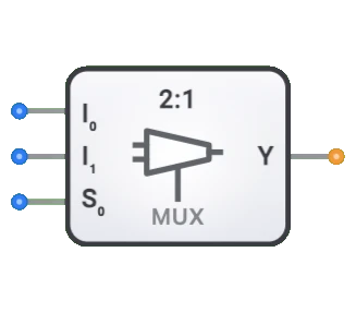
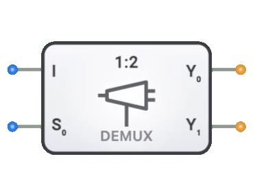
- Symbol: The Demultiplexer is represented by a rectangular block with a single data input, a select input, and two output lines.
- DigiSim.io Role: Serves as a fundamental 1-to-2 data distribution component in digital circuits, enabling signal routing, address decoding, and implementing complex digital systems.
Functional Description
Logic Behavior
The Demultiplexer directs the input signal to one of two outputs based on the value of the select input. When Sel=0, the Data input is routed to Y0 while Y1 is held at 0. When Sel=1, the Data input is routed to Y1 while Y0 is held at 0.
Truth Table (1-to-2 Demultiplexer):
| Data | Sel | Y0 | Y1 |
|---|---|---|---|
| 0 | 0 | 0 | 0 |
| 0 | 1 | 0 | 0 |
| 1 | 0 | 1 | 0 |
| 1 | 1 | 0 | 1 |
Note: When Data is 0, both outputs are 0 regardless of the select input.
Inputs and Outputs
Inputs (2 total):
- Data: 1-bit data input that will be directed to one of the two outputs.
- Sel: 1-bit select input that determines which output receives the data signal.
Outputs (2 total):
- Y0: Output that receives the Data input when Sel=0.
- Y1: Output that receives the Data input when Sel=1.
Configurable Parameters
- Propagation Delay: The time it takes for the outputs to change after a select or input change.
Visual Representation in DigiSim.io
The Demultiplexer is displayed as a rectangular block with a single data input on one side (typically the left), a select input usually at the bottom, and two outputs (Y0, Y1) on the opposite side. When connected in a circuit, the component visually indicates the active output path through color changes on connecting wires.
Educational Value
Key Concepts
- Data Distribution: Demonstrates how a single signal can be routed to different destinations.
- Binary Decoding: Illustrates how binary values can be decoded to select specific outputs.
- Digital Switching: Shows how digital systems can dynamically redirect signals.
- One-to-Many Operations: Introduces the concept of distributing a signal to multiple potential recipients.
Learning Objectives
- Understand how demultiplexers direct data flow from one source to multiple destinations.
- Learn the relationship between binary select codes and active outputs.
- Recognize how demultiplexers can be used for address decoding in memory systems.
- Apply demultiplexers in designing data distribution systems.
- Comprehend the complementary relationship between multiplexers and demultiplexers.
Usage Examples/Scenarios
- Address Decoding: Selecting specific memory chips or peripherals based on address values.
- Data Distribution: Routing data from a single source to multiple destination devices.
- Serial-to-Parallel Conversion: Distributing bits from a serial stream to parallel outputs.
- Control Signal Routing: Directing control signals to specific components in a larger system.
- Display Systems: Selecting individual segments or digits in multi-element displays.
Technical Notes
- The number of select lines (S) and the number of outputs (Y) have a relationship: 2^S = Y. The DigiSim.io 1-to-2 demultiplexer uses 1 select line (2^1 = 2 outputs).
- Demultiplexers are often used in conjunction with multiplexers to create complete data routing systems.
- A demultiplexer can be thought of as a decoder with an enable input that acts as the data input.
- For active-low systems, the inactive outputs may be HIGH instead of LOW, with only the selected output being LOW when the input is LOW.
Characteristics
- Channel Count: Described as 1:N (e.g., 1:2, 1:4, 1:8, 1:16)
- Select Lines: log₂(N) select inputs to choose among N outputs
- Propagation Delay: Time between input change and stable output
- Fan-Out: Number of logic gates it can drive from each output
- Power Consumption: Typically increases with channel count
- Enable Control: Some demultiplexers include an enable input
- Data Width: Can be 1-bit or multi-bit (bus demultiplexers)
- Glitch Immunity: Quality of avoiding transient incorrect outputs during transitions
Types of Demultiplexers
Binary Demultiplexers
- 1:2 (1 select line)
- 1:4 (2 select lines)
- 1:8 (3 select lines)
- 1:16 (4 select lines)
Bus Demultiplexers
- Handle multiple bits in parallel
- Common widths: 4-bit, 8-bit, 16-bit, 32-bit
Active-Low Demultiplexers
- Output is active when low
- Common in certain logic families
Active-High Demultiplexers
- Output is active when high
- Standard behavior in most digital systems
Tree Demultiplexers
- Constructed by cascading smaller demultiplexers
- Used for large-scale implementations
Applications
Data Distribution
- Distributing signals to multiple destinations
- Memory bank selection
- I/O port selection
Address Decoding
- Memory address decoding
- Peripheral device selection
- Chip select generation
Communication Systems
- Time-division demultiplexing
- Channel separation
- Data stream distribution
Control Systems
- Operation mode distribution
- Control signal routing
- State machine implementations
Data Storage
- Memory write enable control
- Storage bank selection
- Register file addressing
Display Systems
- Segment selection in displays
- Matrix addressing
- Pixel selection
Implementation
Demultiplexers can be implemented using:
Basic Logic Gates
- AND gates with decoder structure
- Combination of decoder and AND gates
Integrated Circuits
- 74xx series:
- 74139: Dual 1:4 demultiplexer
- 74138: 1:8 demultiplexer
- 74154: 1:16 demultiplexer
- 74xx series:
Transistor-Level
- CMOS transistor networks
- Pass transistors
- Tri-state buffers
HDL Designs (Verilog/VHDL)
- Case statements
- Conditional assignments
- Parameterized designs
Circuit Implementation (1:2 DEMUX)
A basic 1-to-2 demultiplexer can be implemented using basic logic gates:
graph TB
    Data[Data] --> AndGate0[AND Gate]
    Data --> AndGate1[AND Gate]

    Sel[Sel] --> NotGate[NOT Gate]
    Sel --> AndGate1
    NotGate --> AndGate0

    AndGate0 --> OutputY0[Y0]
    AndGate1 --> OutputY1[Y1]
Boolean Equations (1:2 DEMUX)
For the 1-to-2 demultiplexer with data input D, outputs Y0 and Y1, and select input S:
- Y0 = D • S̅
- Y1 = D • S
Where • represents logical AND and ̅ represents logical NOT
Related Components
- Multiplexers: Perform the reverse operation (N-to-1 routing)
- Decoders: Convert binary code to multiple output lines
- Encoders: Convert multiple input lines to binary code
- Bus Transceivers: Bidirectional data transfer with direction control
- Data Distributors: Similar to demultiplexers but with different control logic
- Address Decoders: Specialized demultiplexers for memory addressing
- Digital Switches: Electronic equivalents of mechanical switches
- Demultiplexer Trees: Cascaded demultiplexers for large output counts